Home :
![]()
COMPUSAT SUPPORT INFORMATION Adding Satellite Receivers
|
|
This page provides support for adding receivers to your CompuSat system
New receivers may be added to CompuSat by configuring the new device in your SIT data. You will need the following information before getting started:
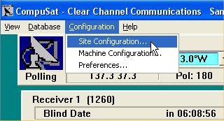
Add the receiver to the site configuration To access site configuration, click the Configuration menu choice and select Site Configuration. NOTE: You must be logged in with administrator rights to access the site configuration dialog.
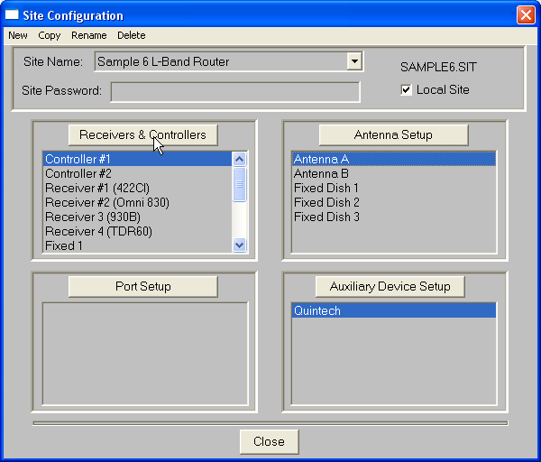
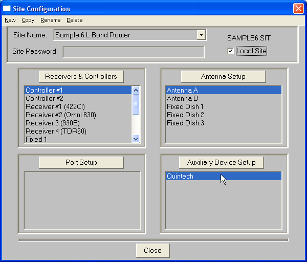
When you select Site Configuration, the following dialog is displayed:
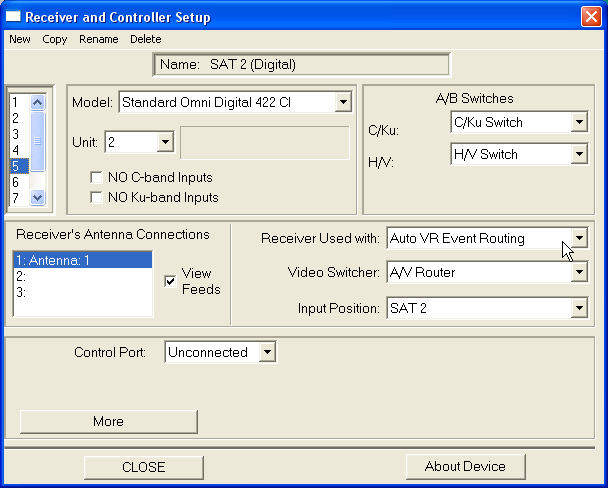
Click on the Receivers & Controllers button to display the receivers and controllers editor.
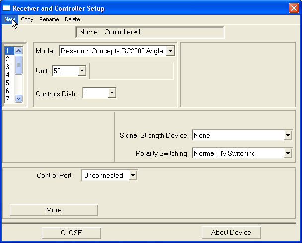
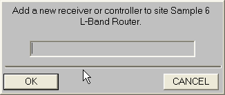
NOTE: The column of numbers in the upper left is a quick index to all the devices defined in the receivers and controllers site data. You can edit/examine other devices quickly by highlighting one of the numbers. Clicking the New menu choice will instruct you to enter the name for the new device. This is the name that will display on the CompuSat front panel.
Enter the receiver's name and click OK.
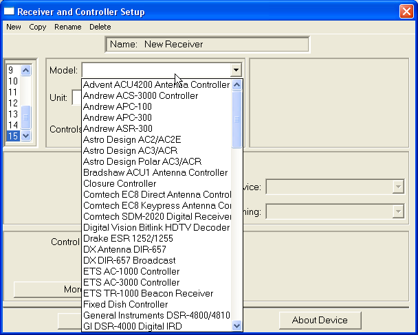
Next, click the Model pick list and select the make and model of the receiver you are adding.
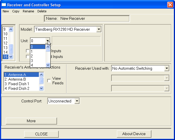
If the Unit pick list appears, set the value to match the address programmed into the receiver's firmware. Please refer to the specific installation instructions for details on how to examine and/or change the address of the receiver (here).
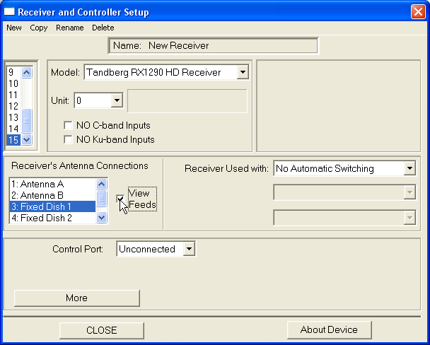
Highlight the antenna(s) this receiver is connected to and click the View Feeds checkbox. As you highlight each antenna, the View Feeds checkbox should only be checked on antennas this receiver can receive signals from. For a receiver dedicated to an antenna, only one antenna should be checked. For a receiver connected to an RF Matrix, all the antennas on the matrix should be checked. Some receivers allow you to use the multiple RF inputs on the receiver to connect to multiple antennas. The More dialog for each receiver has configuration options for this feature when available. If this receiver can only receive a single band and is connected to a multi-band antenna, check either to No C-band Inputs or No Ku-band Inputs to restrict the channel choices to the only those on the available band. Click the Control Port pick list to select the serial port used for this receiver. CompuSat will automatically select the default serial parameters for this receiver model.
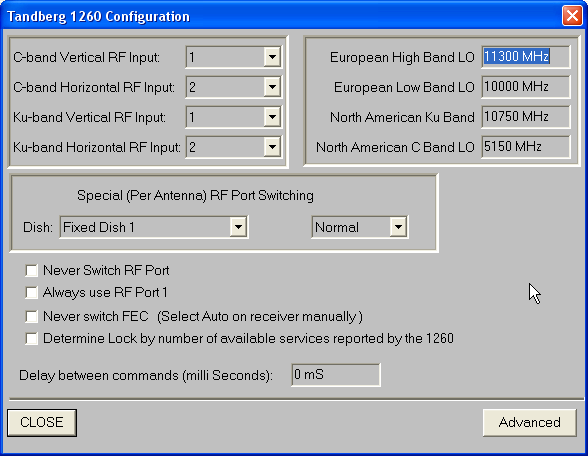
Many receivers have additional configuration parameters defined in the More dialog. These configurations are specific to the receiver's model. An example is shown below. Please refer to the specific installation instructions for details on the More dialog for each receiver (here).
The upper left section defines how which RF ports will be used when tuning a specific band. The upper right section defines the standard LO offset for each band. These should be left a defaults. NOTE: Changes to the More dialog do not take effect until a Reset Communications is performed on the receiver. Open the receiver's monitor screen from the front panel to access Reset Communications. Acquisition Systems For acquisition systems, the receiver's router source must be defined:
Click the Receiver Used with pick list and select Auto VR Event Routing. Next, click the Video Switcher pick list and select the A/V router this receiver is connected to. Finally, click the Input Position pick list and select the router source name corresponding to this receiver. L-band Matrix Systems For L-band Matrix systems, the receiver's matrix destination must be defined. Edit the L-band matrix device in Site Configuration under the Auxiliary Device Setup list and double clicking the L-band matrix device:
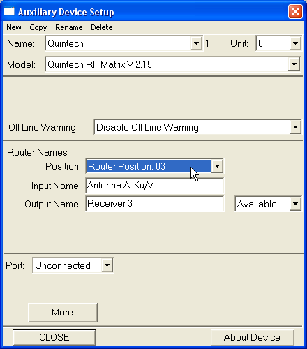
Highlighting Quintech and clicking Auxiliary Device Setup or double-clicking Quintech will display the configuration screen for the Quintech.
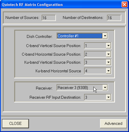
Click on the Position pick list and select the destination number that feeds this receiver. Type in the receiver's name in the Output Name field. This is for labeling purposes on for display on the L-Band XY panel. For the automatic router switching configuration, click the More button. The following dialog is displayed:
Click the Receiver pick list and select the new receiver's name. Next, click the Receiver RF Input Destination pick list and select the destination number that feeds this receiver on the matrix. NOTE: Changes to the L-band more screen do not take effect until CompuSat recalculates and draws the front panel screen. You can force this by going to Configuration/Preferences and changing any of the check-boxes, change it back. and then exiting preferences.
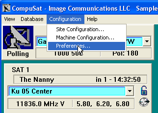
The drawing preferences dialog provides control over the receiver display process. Click Configuration/Preferences:
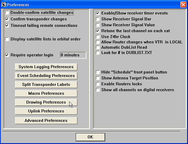
to display the Preferences dialog:
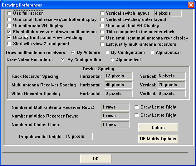
Click Drawing Preferences to display the Drawing Preferences Dialog:
Movable antennas The movable antennas are displayed across the top of the CompuSat display. The number of antenna's that can be viewed on one view depends on the display resolution of the monitor and a number of display setting parameters. The higher the screen resolution, the more antenna's that will fit across the top of your display. You may also adjust the following display parameters: The Use small font receiver/controller display changes the font used for the antenna controller and associated receiver display to use a smaller font, thus saving space allowing for more antennas across the top of the display. The Fixed dish receivers drawn multi-antenna saves horizontal space by electing not to show fixed antenna's as controllers at the top of the CompuSat display. This saves room to display the controllers you actually need to move. The receivers connected to the antenna will be drawn as if they were connected to multiple antenna's with the fixed antenna the only antenna they can choose. These receivers are drawn in an XY grid below the dedicated receivers and above any VR devices. We recommend checking this option unless you have a specific reason not to. The Rack Receiver Spacing fields control the spacing between columns of movable receivers and rows of receivers. When trying to make extra devices fit, set all the spacing to 0. Increase the amount for readability after you get the extra devices to display. Normally, we do not display fixed antennas on the CompuSat Front Panel as they take up room and generally are not needed. CompuSat will always display a fixed antenna if the antenna has an uplink attached. You may also elect to display the fixed antenna just like the movable antenna's just for organization sake if you have the space. Normally, we will check the Fixed dish receivers drawn multi-antenna checkbox to remove the fixed antenna from appear across the top of the CompuSat Front Panel display. The Fixed dish receivers drawn multi-antenna saves horizontal space by electing not to show fixed antenna's as controllers at the top of the CompuSat display. This saves room to display the controllers you actually need to move. The receivers connected to the antenna will be drawn as if they were connected to multiple antenna's with the fixed antenna the only antenna they can choose. These receivers are drawn in an XY grid below the dedicated receivers and above any VR devices. The drawing preferences dialog provides control over the receiver display process. Click Configuration/Preferences and then click Drawing Preferences to display the following dialog:
Check the fourth checkbox, Fixed antenna receivers drawn multi-antenna. You can control the sort order by selecting a Draw Video Recorders radio button option. You can control the numbers of rows of multi-antenna receivers by adjusting the Number of Fixed Receiver Rows value. You can further control the display order by selecting Draw Left to Right. If not selected, the receivers will be populated from the top to the bottom of each column. The Fixed Receiver Spacing controls the number of horizontal and vertical pixels between receivers. Receivers connected to a single movable antenna The movable antennas are displayed across the top of the CompuSat display. Receivers dedicated to a movable antenna are drawn below the antenna display. The number of receivers that can be displayed for each movable antenna depends on the display resolution of the monitor and a number of display setting parameters. The higher the screen resolution, the more receivers that will fit on your display. You may also adjust the following display parameters: The Use small font receiver/controller display changes the font used for the antenna controller and associated receiver display to use a smaller font, thus saving space allowing for more antennas across the top of the display. The Rack Receiver Spacing fields control the spacing between columns of movable receivers and rows of receivers. When trying to make extra devices fit, set all the spacing to 0. Increase the amount for readability after you get the extra devices to display.
Receivers connected to a single fixed antenna The Fixed dish receivers drawn multi-antenna saves horizontal space by electing not to show fixed antenna's as controllers at the top of the CompuSat display. This saves room to display the controllers you actually need to move. The receivers connected to the antenna will be drawn as if they were connected to multiple antenna's with the fixed antenna the only antenna they can choose. These receivers are drawn in an XY grid below the dedicated receivers and above any VR devices. We recommend checking this option unless you have a specific reason not to.
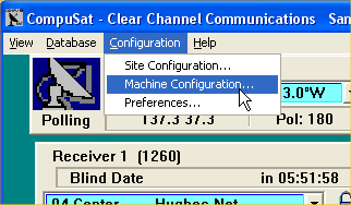
Receivers connected to multiple antennas The multi-antenna receivers are drawn in an XY grid below the bottom movable antenna dedicated receiver and above the recorder devices or the status bar if no recorder devices are present. The number of receivers that can be displayed depends on the display resolution of the monitor and a number of display setting parameters. The higher the screen resolution, the more receivers that will fit on your display. You may also adjust the following display parameters: The Use small font muti-antenna rcvr display changes the font used for the receiver display to use a smaller font, thus saving space allowing for more receivers across the display. The Draw multi-antenna receivers radio button control changes the display order. Click on Alphabetical to sort the multi-antenna receivers in alphabetical order. The Fixed Receiver Spacing fields control the spacing between the rows and columns of multi-antenna receivers. When trying to make extra devices fit, set all the spacing to 0. Increase the amount for readability after you get the extra devices to display. The Number of Fixed Receiver Rows sets the number of rows CompuSat will use when drawing the CompuSat Front Panel. The number of columns depends on the screen resolution, spacing and fonts. The Draw Left to Right checkbox control the sort order. If checked, the sorted multi-antenna receivers names will be drawn from left to right starting at row one. If unchecked, the sorted receiver names will be drawn vertically starting with column 1. The machine configuration dialog provides control over the receivers displayed in each view. Click Configuration/Machine Configuration:
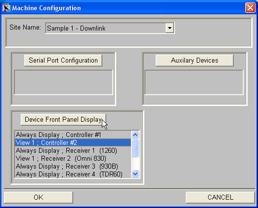
to display the Machine Configuration dialog:
Highlight the receiver you want to adjust and click the Device Front Panel Display button or simply double-click the antenna controller you want to adjust.
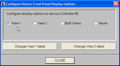
The Configure Device Front Panel Display Options is displayed for the selected device. Click which views you want this antenna to be included with and then click Close. Note: If the antenna controller does not display in a view, none of the receivers dedicated to the antenna will display. No need to set the display options for these receivers.
|

Any questions? Call Image Communications, LLC @941-322-2534 |
| Contact Us | Copyright © 1991-2008 Image Communications, LLC | Image Communications, LLC |